A Real-Time Infrared Tracking System for Virtual Environments
by Maxim Foursa
Tracking, also called position and orientation tracking or position tracking and mapping, is used in Virtual Environments where the orientation and the position of a real physical object is required, for example to interact directly with the 3-D objects rendered by the virtual environment system. An optical tracking system has been developed in the laboratory of Virtual Environments (VE) of the Fraunhofer Institute for Media Communication in collaboration with the Russian Institute of Computing for Physics.
The optical tracking system operates on a standard PC platform and includes three cameras and a frame grabber. The system is able to track the position and orientation of a user's head and stylus in a CAVE-like volume. Active LEDs generate optical markers, which are acquired by the cameras. The system follows events in real time, processing 25 image frames per second. The estimated latency is below 100ms and the measured accuracy of reconstruction of marker position in space is below 5mm. Since this system uses commodity hardware and internally developed software, the price of the system is around 4000 Euro for the the configuration with three cameras and 3300 Euro for the configuration with two cameras.
Specifying a point in three dimensions requires the transition position, that is, the Cartesian coordinates x, y, and z. However, many VE applications manipulate entire objects and this requires the orientation to be specified by three angles known as pitch (elevation), roll, and yaw (azimuth). Thus, six degrees of freedom form the minimum required to fully describe the position of an object in 3-D.
Trackers are used to measure the motion of the user's head or hands, and sometimes eyes. This information is then used to calculate the correct perspective projection and auditory input according to the user's position.
Tracking may be performed using a number of different methods: there exist magnetic, mechanical, optical, acoustic (ultra-sonic), and inertial head trackers. These types of trackers can also be mounted on glove or body-suit devices to provide tracking of a user's hand or some other body part.
 |
|
Figure 1: System setup.
|
For example, in the case of magnetic sensors, a receiver is placed on the user's head so that when the head moves, so does the position of the receiver. The receiver senses signals from the transmitter, which generates a low-frequency magnetic field. The user's head motion is sampled by an electronic unit that uses an algorithm to determine the position and orientation of the receiver in relation to the transmitter.
With almost all of these systems, the user has to be linked to a measurement instrument, via either a cable or, even more restrictive for the user, a mechanical linkage. Furthermore, while mechanical tracking systems are extremely precise, magnetic and acoustic tracking systems suffer from distortion originating from a number of sources. Furthermore, since magnetic systems use magnetic fields, which are generated proximal to the user, it is not safe for people to spend extended times using them. For this reason, we started developing an optical tracking system, which should overcome many of the drawbacks of conventional tracking systems.
 |
 |
|
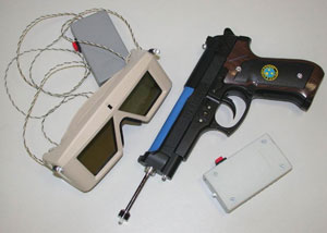
Figure 2: Devices to track.
|
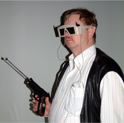
Figure 3: User with the tracking devices.
|
Optical tracking systems can work fast over a large area and be comfortable to use, but are limited by light source intensity and require a line of sight from emitter to receiver. Though high-quality, precise optical systems are quite expensive, we have demonstrated that it is possible to make a simple system that meets the requirements of user-VE-user interaction, on the basis of commodity hardware and complex multi-step software processing.
Our system employs three near-infrared monochrome cameras JAI-M50IR, which are equipped with 6mm lenses and infrared filters and are installed in a test laboratory above a reflective screen. These cameras are attached to an RGB frame grabber. The output from the frame grabber is one image with the size 769x570 that contains synchronised output from all the cameras in the R, G and B planes. The scanning speed of the frame grabber is 25 frames/sec. This output is processed on a workstation with Pentium 4 2.2GHz processor, using specially developed software. To resolve the objects being tracked, we are using active infrared beacons. Currently we have three devices to track: a pointer with one LED emitter, shutter glasses with two LEDs and a pointer with three LED emitters and a telescopic tube, for better direction reconstruction. The power supply for the devices is a 9V battery. The direct current is constant and can be varied from 5mA to 50 mA.
The general scheme of operations is the following. The first step after the frame grabber acquires the three images is the beacon detection. It can operate in two different modes. The first mode is a global search over the whole image data in one colour plane (that is the output from one camera) for a detection of all beacon positions. If the system knows the last two calculated positions, the second mode will do a local search because a prediction has restricted the area of interest. When we have all beacon positions on the image from one camera, we can calculate the epipolar line and optimise the search process on other cameras by doing it in the vicinity of the line. To get the coordinates of a beacon, the program looks for a light spot ellipse (the motion causes an ellipse rather than a circle) and determines its radii. The next step is a 2-D transformation from distorted image coordinates to undistorted camera sensor coordinates. Afterwards, the epipolar constraint can be used to get the correlated image points, as well as other constraints defined by beacon positions or sizes, and as a result, we obtain the 3-D positions which we can assign to corresponding devices.
For calibration we use a two-step method: to get the internal camera parameters we use an implemetation of the Tsai method, and to get its position and orientation we use the Faugeras method and a special target which has more than thirty points measured by a theodolite with high accuracy in a coordinate system.
The system is currently installed in the CyberStage VE system at Sankt-Augustin and is being used instead of or with the Polhemus FASTRACK magnetic tracking system. The CyberStage is a 3m x 3m CAVE with stereoscopic projections on all four walls and the floor, and with 8-track sound and vibrating floor. The tracking server transmits the data via the network to a listening daemon, which processes them for AVANGO programming framework, which then renders the virtual scene. The system is flexible and can be adjusted for the use in other virtual environments, if the lighting conditions (eg the absence of bright light, such as sunlight or the light emitted by CRT monitors) allow it. It is anticipated that the system will be used in the Russian Institute of Computing for Physics and Technology in low-cost VR projects.
Please contact:
Maxim Foursa, FhG-IMK
Tel: +49 2241 12 2773
E-mail: maxim.foursa@imk.fhg.de
|